PCB assembly/SMT
 PCB Manufacturing
 Components Sourcing
 PCB design
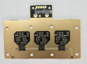
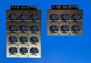
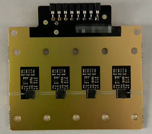
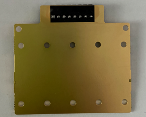
Our company made a RF PCB board for American customers. There are many types of these boards, all of which are used in the communications industry. The characteristic of these boards is that a special RF circuit is designed, and the RF circuit is strictly required to have an impedance of 50 ohm. And all 4 sides of the PCB board should be edge plating. The via plug resin is generally designed with blind holes and buried holes in 4 layers. These boards are pressed together by ROGERS and FR4, so the board is very brittle. There are also many precautions during the SMT process.Since the thickness of the board and the board is 0.8mm, care must be taken to avoid board warping at the end of production. And the packaging of the components is very small, and research is also needed for stencils and SMT. Since the 4 sides of the PCB are all edge plating, you should also pay attention when you join the boardinto panel, otherwise the plated edges will be damaged.
In our RF circuit design, we often encounter a special impedance-50Ohm. Why must it be 50 Ohm? Isn’t 10Ohm or 100Ohm OK? With this question, let’s take a look at it together?
The standardization of 50 ohm impedance can be traced back to coaxial cables developed for kilowatt radio transmitters in the 1930s. A. S. Gilmour, Jr. gave a good explanation for choosing 50 ohms in “Microwave Tubes”. The answer is: For air dielectric coaxial cables, 50 ohms is the balance between power capacity and loss.
Radio Frequency (RF) is short for Radio Frequency, which represents the electromagnetic frequency that can be radiated in space and the frequency ranges from 300kHz to 300GHz. Radio frequency is radio frequency current, referred to as RF, which is an abbreviation for high frequency alternating electromagnetic waves. Alternating current that changes less than 1,000 times per second is called low-frequency current, and that that changes more than 10,000 times is called high-frequency current. Radio frequency is a high frequency current. Radio frequency (300K-300G) is a higher frequency band of high frequency (greater than 10K) and the microwave frequency band (300M-300G) is a higher frequency band of radio frequency.
In the theory of electronics, when current flows through a conductor, a magnetic field is formed around the conductor; when an alternating current passes through the conductor, an alternating electromagnetic field is formed around the conductor, which is called an electromagnetic wave. When the electromagnetic wave frequency is less than 100kHz, the electromagnetic wave will be absorbed by the surface and cannot form effective transmission, but when the electromagnetic wave frequency is more than 100kHz, the electromagnetic wave can propagate in the air and be reflected from the ionosphere to the outer edge of the atmosphere to form long-distance transmission capacities. We call high frequency electromagnetic waves with long distance transmission capability as radio frequencies. Radio frequency technology is widely used in the field of wireless communication and the cable television system uses radio frequency transmission.
Application field
Radio frequency communication
In the entire radio frequency communication, it mainly includes the following frequencies: transmission frequency, reception frequency, intermediate frequency and baseband frequency. The baseband frequency is the frequency of the signal used to modulate the data. The real transmission frequency is much higher than the baseband frequency. The general frequency spectrum ranges from 500MHz to 38GHz, and data signals are also transmitted at this high frequency. Generally speaking, the radio frequency system has a very powerful function of transmitting modulated signals. Even in the presence of interfering signals and blocking signals [z2], the system can transmit with the highest quality and receive with the best sensitivity. Modulated signal. There are two main types of blocking signals: in-band blocking signals and out-of-band blocking signals. Out-of-band blocking signals refer to irrelevant signals distributed outside the signal spectrum, such as data signals generated by other wireless transmission technologies. In-band blocking signals are distributed within the signal spectrum of our interest, such as data signals generated by the same wireless transmission technology in other terminals. For wireless communication, to successfully realize the radio frequency receiving function, these two blocking signals must be filtered out. The intermediate frequency is often used as the transition between the transmission/reception frequency and the baseband frequency, and this transmission method is the basis of the superheterodyne structure. Generally speaking, out-of-band blocking signals can be filtered out by the filter that comes with the antenna. The existence of the intermediate frequency gives us the opportunity to filter out the in-band blocking signal before the signal is mixed to the baseband frequency and digitally processed. On the other hand, at the transmitting end, the intermediate frequency is often used to filter out all the pseudo data and noise that may be generated during the conversion from baseband to intermediate frequency.
Another way to implement a superheterodyne structure is to use intermediate frequency sampling to reduce the number of devices in the signal chain. This method chooses to sample the signal at the intermediate frequency instead of mixing the signal to the baseband before sampling. In the first superheterodyne structure, the conversion process from intermediate frequency to baseband requires the following components: local phase-locked loop, intelligent demodulator (mixer) and bidirectional ADC (analog-digital converter). If you choose to sample at the intermediate frequency, these three devices can be replaced with a high-performance ADC. This not only reduces the complexity of the signal chain, but also improves the quality of signal demodulation.
However, if a high-quality intelligent demodulator is used in the downlink baseband converter, very good communication effects can also be obtained. If the leakage of the local phase-locked loop and radio frequency components can be made small enough, the DC offset of the baseband can be minimized. In addition, the phase separation function of the demodulator can achieve a very accurate 90-degree phase separation, which will ensure that the value of the error vector will not deteriorate or just deteriorate a little when the signal is demodulated. Finally, if we use a phase-locked loop with low phase noise while using an intelligent demodulator, it will ensure the low noise of the baseband output signal and thus obtain a good bit error rate (BER).
Because the ADC has to work at higher and higher frequencies, the power consumption of the IF sampling structure becomes higher and higher than that of the first superheterodyne structure, and therefore it becomes more and more expensive. This is the most expensive of the IF sampling structure. The main disadvantage. For this reason, radio frequency structures based on intermediate frequency sampling are often more suitable for applications at relatively low or intermediate frequencies. After all, these frequency bands have little effect on cost. However, with the development of technology, especially the introduction of CMOS technology, the price of integrated high-performance devices and circuits is getting lower and lower. In the near future, the intermediate frequency sampling structure will no longer be an expensive choice.
The third structure applied in radio frequency communication is because the direct conversion structure directly mixes baseband signals and radio frequency signals in the same process, which makes the signal link of this structure the simplest and requires the least components. Unlike the other two structures, it will not require intermediate frequency processing and surface acoustic wave (SAW) filters.
The main advantages of the direct conversion structure are: low price, miniaturization, low power consumption, and no intermediate frequency conversion related devices. These advantages make this structure very suitable for low-power, portable terminal applications. Nevertheless, the use of some high-performance devices has opened the door for direct conversion structure applications in the high-end market. In fact, it is the use of these high-performance devices that make direct conversion structures receive more and more attention.
Since there is no intermediate frequency processing unit in the direct conversion structure, the power of the in-band blocking signal will be directly passed to the mixer and the analog-to-digital converter (if the signal link contains the analog-to-digital converter). A low-noise mixer will ensure that weak signals will not be overwhelmed by noise and blocked signals. In addition, because the mixer has a high output swing and low distortion, the blocking signal will neither overdrive the entire system nor modulate the carrier signal we need.
For a baseband superheterodyne receiver, if there is a leakage path between the local phase-locked loop and the RF input, a DC offset will definitely occur. For some radio frequency applications that support frequency hopping similar to the global mobile communication system, the frequency hopping will cause the leakage of the local phase-locked loop to change, and eventually lead to the jump of the DC offset of the entire system. If you want to correct it, you must introduce a DC offset compensation loop into the system. Nevertheless, in those applications that do not require frequency hopping, the leakage of the local phase-locked loop is constant, so the compensation of dynamic DC offset is of little significance.
At the transmission end, since the in-band noise and distortion cannot be effectively reduced, the radio frequency transmitter using the direct conversion structure must be composed of those components with a large dynamic range.
In the relevant application of the base station, because the area and channel density must be considered, the direct conversion structure is especially promising. From the perspective of the base station, the in-band blocking signal does not exist (that is, the base station will process the in-band blocking signal), so even if the direct conversion structure lacks the function of filtering out the in-band blocking signal, it is acceptable of.
Of course, the choice of radio frequency circuit structure should be determined by market applications. These guiding design factors include: time from design to market entry, cost, shape, functional indicators, flexibility, whether it can support a variety of different application modes, and so on. How to select the appropriate radio frequency structure for a certain application is beyond the scope of this article. But what is clear is that nowadays some RF device manufacturers can already provide a variety of targeted services to help us design a suitable RF system. During the entire structural design process, they can even provide several experienced engineers for us. FAQ.
Medical applications
Radio frequency wrinkle reduction is a non-invasive treatment method, and one of the safest and most effective cosmetic wrinkle removal methods.
The principle of radio frequency wrinkle removal is: radio frequency waves penetrate the barrier of epidermal basal melanocytes to heat the collagen fibers in the dermis to 55°C-65°C, and the collagen fibers shrink, so that the loose skin wrinkles are tightened, so as to achieve beauty and wrinkle removal. Purpose.
Features of RF wrinkle removal
Feature 1: High efficiency. Experiments have shown that radio frequency wrinkle removal can effectively stimulate collagen reorganization, tighten the skin, reduce wrinkles, and have a higher satisfaction after treatment.
Feature 2: Safety. The radio frequency wrinkle removal system can protect the epidermis to achieve satisfactory results that are both safe and efficient. It is safer than other non-invasive treatments. In addition, there is no recovery period after treatment, and patients can resume their daily routines immediately, eliminating other necessary precautions after treatment.
Feature 3: Lasting, after treatment, the skin will be improved every day due to the continuous production of new collagen. And it will achieve more significant and satisfactory results in about 4-6 months.
recognition system
Radio frequency identification technology can be divided into two categories: low frequency system and high frequency system according to the frequency used; according to whether the electronic tag is equipped with battery for power supply, it can be divided into active system and passive system. ; The method of injecting the information stored in the electronic tag can be divided into three categories: integrated circuit solidification, on-site wired rewriting and on-site wireless rewriting;
according to the technical means of reading electronic tag data, it can be divided into There are three types of broadcast transmission type, frequency multiplication type and reflection modulation type. [4]
1. Low-frequency systems generally refer to their operating frequencies less than 30MHz. Typical operating frequencies are: 125KHz, 225KHz, 13.56MHz, etc. The radio frequency identification systems used at these frequencies are generally supported by corresponding international standards. Its basic characteristics are the low cost of the electronic tag, the smaller amount of data stored in the tag, and the short reading distance (passive case, the typical reading distance is 10cm). The electronic tag has various shapes (card-shaped, ring-shaped, button-shaped, Pen shape), the reading antenna is not directional, etc.
2. High frequency system generally refers to its operating frequency greater than 400MHz, typical operating frequency bands are: 915MHz, 2450MHz, 5800MHz, etc. High-frequency systems are also supported by numerous international standards on these frequency bands. The basic characteristics of the high-frequency system are that the cost of electronic tags and readers are relatively high, the amount of data stored in the tags is large, the reading distance is relatively long (up to a few meters to ten meters), and it has good performance in adapting to high-speed movement of objects, and the appearance is generally a card. The shape, reading antenna and electronic tag antenna have strong directivity.
3. There is a battery in the active electronic tag, which generally has a long reading distance. The disadvantage is that the battery life is limited (3~10 years); there is no battery in the passive electronic tag, and it receives the reader (reading device). After the microwave signal is generated, it converts part of the microwave energy into direct current for its own work. Generally, it can be maintenance-free. Compared with the active system, the passive system has a slight limitation in the reading distance and the speed of adapting to the movement of the object.