 PCB assembly/SMT
 PCB Manufacturing
 Components Sourcing
 PCB design
After the design of an electronic product is completed, we need to find a cost-effective factory to try out samples. After the samples have been tested and improved, they will be put into mass production. When choosing a factory, in addition to some certifications, it is best that the factory can provide one-stop service. Otherwise, the purchase of PCBs, components, and assembly will eventually be merged into the processing plant, which will cause a lot of losses in communication costs, transportation costs, and so on. And if the product is defective, several parties will not shirk each other’s responsibilities, because there are many reasons for the defective PCBA, which may be PCB, or component and assembly problems. So entrust a factory to provide one-stop service, which is more traceable.
After selecting several assembly factories, we need to provide the factory with information for quotation. Simply put: gerber, BOM, pick&place file. These three points are the most important and necessary.
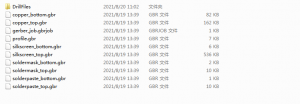
gerber file.
Gerber mainly gives information about PCB. You can also provide a .PCB file, and you can use the PCB file to gerber everywhere. The two are equivalent. We can confirm the number of layers and dimensions of the PCB through gerber. These two points are important factors that affect the price of PCB. In addition, the designer will add a description file to the gerber to describe the surface technology of the PCB, solder mask color, silk screen color, via requirements, etc. You can also specify additional requirements when contacting the factory quotation staff. For the quotation of PCB price, the most important thing is the size, number of layers, surface technology, internal structure (whether there are blind holes, buried holes, etc.)
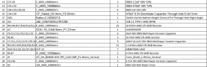
BOM list(Bill of material)
This is a table of all the electronic components that will be soldered on the PCB. There are some necessary information in the BOM. If you lack it, you cannot quote. There must be a useful amount in the BOM, the position number is like C1, C2, U9, L3… package, the most important is the model. Because the model is composed of a string of letters and numbers, there is no duplication. It is easy to search for specific components by searching for the model number. When the model number is not provided, the value, accuracy, etc. of some components must be provided. There are some special electronic components, we can add some pictures or links after the corresponding items, so that the factory can clearly understand what the specific components are, and ensure the efficiency and accuracy of the quotation.
BOM is a very important component. The IQC of the factory will compare the materials and the BOM item by item. All information must be consistent to ensure that accurate materials are purchased. IQC will also compare each material separately with the pads on the PCB to ensure that the component packaging and pads match. And any questions will immediately contact the customer for confirmation. Because of the many projects we have done, some customers have designed PCBs and BOMs that do not match, some have wrong materials, and some components need to confirm the direction and polarity, and so on. These will be discovered and resolved using BOM before production. Our company will also update the revised BOM in time to ensure that the BOM used next time is accurate.
pick&place file
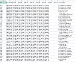
The pick&place file is a file used for programming by SMT engineers. It can be a TXT file or an excel file, which is provided by the designer. You can also export the pick&place file from the .pcb file. First, it is used to program the SMT machine so that the machine can prepare to place each component in the correct position on the PCB board. Second, pick&place file reflects the coordinate information, position number, and parameters of each component. This corresponds better to the BOM and can be confirmed again. For how to export the pick&place file from the .pcb file, we will introduce it in detail later. In addition, some designers will export the top pick&place file and bottom pick&place file of the PCB respectively. It is stated here that DIP components do not need pick&place file. Because DIP components require manual or manual participation in jig welding. The pick&place file is used to become an SMT machine.
Below is a SpeedMeter PCBA board pick&place file as a example:
In addition to the three necessary documents mentioned above, we had better provide the following reference documents.
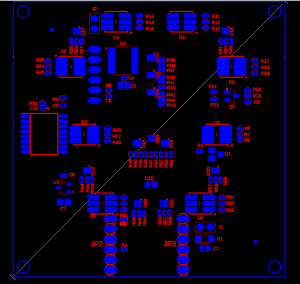
First: the top-level drawings of the PCB, and the bottom-level drawings. Also, mark the positive and negative poles next to the components with polarity. Because the components with polarities are in the wrong direction, the PCBA will not work either.
Second: 3D reference map. If there are physical photos, it is best to provide clear physical photos. If it is a newly designed project, it is best to have a 3D drawing for the factory’s reference.
In addition, an important piece of information is to inform OEM factories whether they can replace electronic components. According to different product grades and requirements, it can be clearly stated that no substitutions will be accepted. Or it can be stated that substitutes with the same function are accepted, because some substitute components are very advantageous in terms of quality, delivery time and price.
So first you need to design the product and provide the above-mentioned documents. The second is to choose an experienced factory. Basically the problems that arise like this, the factory can solve them for you。